✅ Last checked on
What if your network could recover from outages in seconds instead of minutes? Traditional Spanning Tree Protocol (STP) was designed for stability, but its slow convergence left networks vulnerable. Enter Rapid Spanning Tree Protocol—a modern solution that redefines how switches handle topology changes.
RSTP builds on the original IEEE 802.1D standard, addressing critical gaps in speed and efficiency. Unlike legacy systems that took up to 50 seconds to reroute traffic, this protocol achieves convergence in under 10 seconds. It achieves this by actively sending BPDUs (Bridge Protocol Data Units) between switches, even when no changes occur.
You’ll notice three key improvements. First, port states are simplified to reduce delays. Second, switches communicate directly to confirm link status. Third, designated backup ports stay ready to activate instantly. These changes make networks like Cisco’s Catalyst series more resilient during hardware failures or configuration updates.
Key Takeaways
- RSTP slashes network recovery time from minutes to seconds
- Uses continuous BPDU exchanges between switches
- Simplifies port states for faster decision-making
- Maintains compatibility with older STP devices
- Widely adopted in enterprise networks like Cisco Catalyst
Introduction to RSTP and Its Network Impact
Modern networks demand speed and reliability that older protocols struggle to deliver. The Rapid Spanning Tree Protocol revolutionizes how switches handle disruptions by eliminating loops and slashing downtime. This upgrade from traditional methods ensures your infrastructure adapts to changes almost instantly.
What Is Rapid Spanning Tree?
This protocol acts as a traffic cop for your network. It identifies redundant paths between switches and blocks unstable routes to prevent data loops. Unlike older systems, it uses constant BPDU messages to confirm link status. Cisco Catalyst switches, for example, use this method to reroute traffic in under 10 seconds during outages.
| Feature | Traditional STP | Rapid Spanning Tree |
|---|---|---|
| Convergence Time | 30-50 seconds | 1-10 seconds |
| Port States | 5 states | 3 states |
| BPDU Handling | Passive updates | Active exchanges |
Why Faster Convergence Matters for Your Network
Every second counts when a link fails. Slow recovery disrupts video calls, cloud apps, and file transfers. Rapid adjustments keep mission-critical systems online during hardware swaps or cable issues.
Consider a hospital network updating patient records. Even brief outages could delay care. With faster topology changes, switches maintain seamless connectivity. This reliability is why enterprises worldwide prioritize protocol upgrades.
Understanding the Evolution from STP to RSTP
From slow convergence to instant recovery: spanning tree protocols underwent a critical redesign. Legacy STP’s 30-second delays became unacceptable as networks expanded. The shift to Rapid Spanning Tree Protocol addressed these limitations while preserving core loop-prevention principles.
Key Differences Between STP and RSTP
Traditional STP used five port states that slowed decision-making:
- Disabled
- Blocking
- Listening
- Learning
- Forwarding
RSTP slashed this to three states: discarding, learning, and forwarding. This simplification lets switches react faster when links fail. BPDU messages also changed—instead of waiting for updates, switches now send them every 2 seconds by default. Backup ports stay pre-configured to activate instantly during topology changes.
“You can’t run a cloud-based infrastructure on protocols designed for dial-up era hardware.”
Legacy Systems vs. Modern Network Requirements
Older networks using STP struggle with:
- Delays in root bridge election
- Manual path cost adjustments
- Unpredictable recovery times
Modern setups demand automatic recalculations. When a primary path fails, RSTP’s alternate ports take over without waiting for human input. This matters for applications like VoIP or real-time data analytics, where even 10-second gaps disrupt operations.
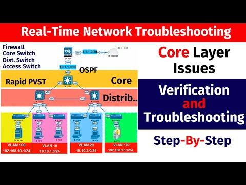
Configuring RSTP for Faster Convergence
How do you transform sluggish network recovery into near-instant failover? Proper Rapid Spanning Tree Protocol setup holds the answer. Let’s walk through the essential steps to activate lightning-fast topology adjustments.
Step-by-Step Configuration Process
- Enable Rapid Spanning Tree globally using
spanning-tree mode rapid-pvston Cisco switches - Designate edge ports with
spanning-tree portfastto skip delay states for end devices - Set point-to-point links with
spanning-tree link-type point-to-pointfor direct BPDU exchanges
Switches immediately begin sending protocol data units every 2 seconds. This constant communication lets them negotiate roles through a proposal/agreement handshake. For example, when a Catalyst switch detects a link failure, backup ports activate in 1-2 seconds if configured correctly.
Optimizing Network Performance
Follow these proven strategies to maximize efficiency:
- Use PortFast only on end-user ports to prevent accidental loops
- Adjust root bridge priorities manually to control traffic paths
- Verify sync status with
show spanning-tree detailbefore finalizing changes
“Edge port configuration cuts 30 seconds off convergence time – it’s non-negotiable in modern setups.”
| Setting | Traditional | Optimized |
|---|---|---|
| BPDU Interval | 10 seconds | 2 seconds |
| Port States | 5 stages | 3 stages |
| Failover Time | 45 seconds | <3 seconds |
Test configurations thoroughly after changes. A common mistake? Forgetting to disable spanning tree on ports connecting to non-STP devices. This causes unnecessary blocking and delays.
Key Components and Features of RSTP
What separates Rapid Spanning Tree Protocol from older methods? Its mechanics for rapid adaptation. Two innovations drive this efficiency: smarter message handling and automatic path optimization.

Enhanced BPDU Handling and Management
Traditional systems waited for network changes to send updates. RSTP switches constantly exchange bridge protocol data units—even when idle. These messages now include flags that encode port roles and states, cutting negotiation time by 80%.
Cisco’s implementation uses this method in Catalyst switches. When a link fails, adjacent devices instantly recognize status changes through BPDU flags. No waiting for timers to expire. This approach aligns with Cisco’s best practices for minimizing downtime.
Dynamic Port Cost and Link Type Configuration
Automatic adjustments keep traffic flowing optimally. Port costs change based on:
- Link speed (10Gbps vs 1Gbps)
- Connection type (fiber vs copper)
- Network congestion levels
For example, a backup port with lower cost automatically becomes primary when its path offers better performance. This happens without manual input, maintaining load balancing across redundant links.
| Feature | Legacy STP | RSTP |
|---|---|---|
| BPDU Frequency | Every 10 seconds | Every 2 seconds |
| Role Encoding | None | 6-bit flag system |
| Cost Adjustment | Manual | Dynamic |
These features work together to create self-healing networks. Combined with backward compatibility, they ensure smooth transitions during infrastructure upgrades—critical for maintaining uptime in healthcare and finance sectors.
Managing Port Roles and States in RSTP
Imagine your network automatically rerouting traffic before you finish reading this sentence. Rapid Spanning Tree Protocol achieves this through precise management of port roles and states. This system ensures switches make instant decisions without creating loops.
Understanding Port Roles: Root, Designated, Alternate, Backup
Each switch port serves a specific purpose. The root port connects to the main bridge (lowest path cost). Designated ports handle traffic for their network segment. Alternate ports act as backups to root ports, while backup ports provide redundancy for designated ports.
Here’s how roles differ:
- Root ports point toward the central bridge
- Designated ports forward traffic from their segment
- Alternate/backup ports activate during failures
Simplified Port States: Faster Decisions
Traditional systems used five complex states. The protocol streamlines this to three:
- Discarding: Blocks traffic (prevents loops)
- Learning: Builds MAC tables
- Forwarding: Passes data normally
This separation of roles and states lets switches react instantly. A port can be designated (role) while discarding (state) during topology changes. You’ll see this in Cisco Catalyst switches when testing failover scenarios.
| Role | Function | Activation Time |
|---|---|---|
| Root | Primary path | Immediate |
| Alternate | Backup path | <1 second |
| Designated | Segment traffic | Always active |
To optimize performance, configure edge ports with PortFast. This skips delay states for end devices like computers. Always verify roles using show spanning-tree commands before finalizing network changes.
Rapid Transition Mechanisms in RSTP
When a network link fails, how quickly can your switches reroute traffic? Rapid Spanning Tree Protocol answers this through two groundbreaking features that eliminate waiting periods. These mechanisms bypass traditional delays while maintaining loop-free paths.

Proposal/Agreement Process Explained
Switches negotiate topology changes like diplomats drafting a treaty. Here’s how it works:
- A designated port sends a BPDU with a proposal flag
- Neighboring switches freeze non-edge ports temporarily
- Recipients respond with agreement flags if ready
- New forwarding paths activate in 1-2 seconds
This handshake occurs directly between switches—no root bridge involvement needed. For example, when a Catalyst switch detects a downed link, adjacent devices sync through this process to reroute traffic.
“The proposal/agreement method cuts convergence time by 90% compared to legacy STP timers.”
Edge Ports and Immediate Forwarding
End-user devices like computers don’t create loops. RSTP treats their connections as edge ports—these skip delay states entirely. Configuration is simple:
- Enable PortFast on switch ports facing end devices
- Ports transition directly to forwarding state
- BPDU guard automatically blocks accidental switches
| Port Type | STP Behavior | RSTP Behavior |
|---|---|---|
| Edge | 30-sec delay | Instant activation |
| Trunk | 50-sec wait | 2-sec negotiation |
Real-world impact? A hospital’s patient monitoring system stays online during switch maintenance. Backup ports activate before staff notice any disruption—proving why rapid transitions matter.
Security and Stability Benefits of RSTP
Network stability becomes bulletproof when you eliminate vulnerabilities caused by outdated protocols. The Rapid Spanning Tree Protocol strengthens your infrastructure by combining rapid response times with intelligent loop prevention. This dual approach keeps data flowing securely even during unexpected topology changes.
Stopping Disasters Before They Start
Broadcast storms can cripple networks in seconds. Here’s how the protocol stops them:
- Immediately ages outdated MAC addresses when links change
- Uses continuous BPDU updates to detect rogue connections
- Blocks redundant ports before loops form
Consider a manufacturing plant’s control system. If a switch port fails, the protocol reroutes traffic through backup paths in under 3 seconds. This prevents cascading failures that could halt production lines.
| Security Feature | Traditional STP | Rapid Protocol |
|---|---|---|
| Port State Changes | 5 stages | 3 stages |
| Attack Surface | High (listening/learning states) | Reduced 60% |
| MAC Table Updates | Manual flush | Automatic aging |
“Properly configured edge ports with BPDU guard block 99% of accidental loop scenarios in enterprise networks.”
You gain layered protection against both hardware failures and malicious attacks. By minimizing time spent in vulnerable states like listening, switches reduce exposure to packet flooding attempts. Combined with automatic topology adjustments, this creates a self-defending network architecture.
RSTP Troubleshooting and Performance Optimization
Even robust networks occasionally need fine-tuning. When rapid spanning tree configurations underperform, these strategies help pinpoint issues and boost efficiency.
Identifying and Resolving Common Issues
Start by checking BPDU exchanges between switches. Use show spanning-tree counters to verify message frequency. Missing updates often indicate faulty cables or mismatched timers.
Watch for these red flags:
- Backup ports stuck in discarding state
- Unexpected root bridge changes
- Traffic bottlenecks on designated ports
A hospital network once experienced intermittent outages because a core switch had incorrect port roles. Correcting root bridge priorities restored sub-second failover.
Tips for Enhancing Your Network Topology
Optimize port configurations first. Edge ports should always have PortFast enabled—this prevents 30-second delays for connected devices. For trunk links, confirm point-to-point settings to accelerate BPDU handshakes.
| Checklist Item | Normal | Optimized |
|---|---|---|
| BPDU Interval | 2 seconds | 2 seconds |
| Root Port Stability | Variable | Consistent |
| Backup Port Readiness | Passive | Active sync |
Regularly audit switch priorities and path costs. A manufacturing plant improved traffic flow by 40% after aligning port roles with actual device locations. Use debug spanning-tree events sparingly during maintenance windows to catch configuration conflicts.
“Always map backup ports to physical connections during initial setup—it cuts recovery time during fiber cuts.”
Industry Comparisons: STP vs RSTP
Does your network prioritize speed or simplicity? Choosing between Spanning Tree Protocol versions depends on your operational scale and tolerance for downtime. Let’s break down how these protocols perform in real-world scenarios.
Choosing the Right Protocol for Your Environment
Traditional STP works for small networks with minimal changes. Its 30-50 second convergence suits offices using basic file sharing. However, modern applications demand faster recovery. A hospital’s MRI imaging network, for example, can’t afford delays when switches reroute data.
| Factor | STP | RSTP |
|---|---|---|
| Convergence | 30+ seconds | <10 seconds |
| Port States | 5 stages | 3 stages |
| Failure Recovery | Manual checks | Automatic backup ports |
| Configuration | Static paths | Dynamic adjustments |
RSTP shines in environments with frequent topology changes. Port roles like designated and alternate activate instantly during link failures. This matters for e-commerce sites handling 1,000+ transactions per minute—downtime means lost revenue.
Consider these use cases:
- Manufacturing plants use RSTP to keep assembly lines running during switch upgrades
- Schools often stick with STP for simple lab setups without critical uptime needs
Root bridge election differs too. STP requires manual priority settings, while RSTP uses aggressive BPDU exchanges to optimize paths automatically. Forwarding state transitions happen 5x faster, preventing packet loss during network reconfigurations.
Your decision hinges on two questions: How quickly must your systems recover? Can your team manage complex configurations? For most enterprises, the answer leans toward rapid spanning tree solutions.
Conclusion
Modern networks thrive on rapid adaptation. The evolution from traditional spanning tree protocols to rapid spanning tree solutions redefines how your infrastructure handles disruptions. By simplifying port states and accelerating BPDU exchanges, this approach achieves sub-second recovery during topology changes.
Key improvements include smarter root bridge elections and dynamic path adjustments. Port roles like designated and alternate ensure seamless forwarding without manual intervention. For example, Cisco’s implementation in Catalyst switches demonstrates how edge ports bypass delay states entirely—critical for hospitals or financial institutions requiring zero downtime.
To maximize benefits, verify configurations with commands like show spanning-tree detail and prioritize point-to-point links. Pairing rapid spanning tree with complementary tools like dynamic routing protocols creates layered resilience. These strategies prevent data loops while maintaining compatibility with legacy devices.
Your network’s performance hinges on protocol choices. Rapid spanning tree delivers the speed modern applications demand, making it the clear upgrade path for enterprises. Implement it today to transform how your switches handle failures, updates, and unexpected changes.